This page contains procedures related to the legacy editor. Try out our new editor that has a more streamlined design and provides a better app editing experience. More info.
This page contains information on how to use the fields of the Inputs tab on the Tool Editor.
On this page:
The Inputs tab allows you to describe the input ports of your tool. A port is a 'gateway' for data to flow in and out of your tool. You should add one input port for each input your tool takes. For instance, if your tool takes a file and an integer as input per execution, you should enter two ports; if it takes two files, one reference and one data file, and does different things to each, then you should also enter two ports.
Note on inputs
Remember that inputs in this sense include parameters that can be adjusted in each execution as well as inputted data, like files.
Add an input port to the tool description
To add an input port to the tool description, go to the tab labeled Inputs on the Tool Editor. Then, click the + button.

Click + to add an input port to your tool description.
This will bring up a pop-up window that allows you to describe an input port.
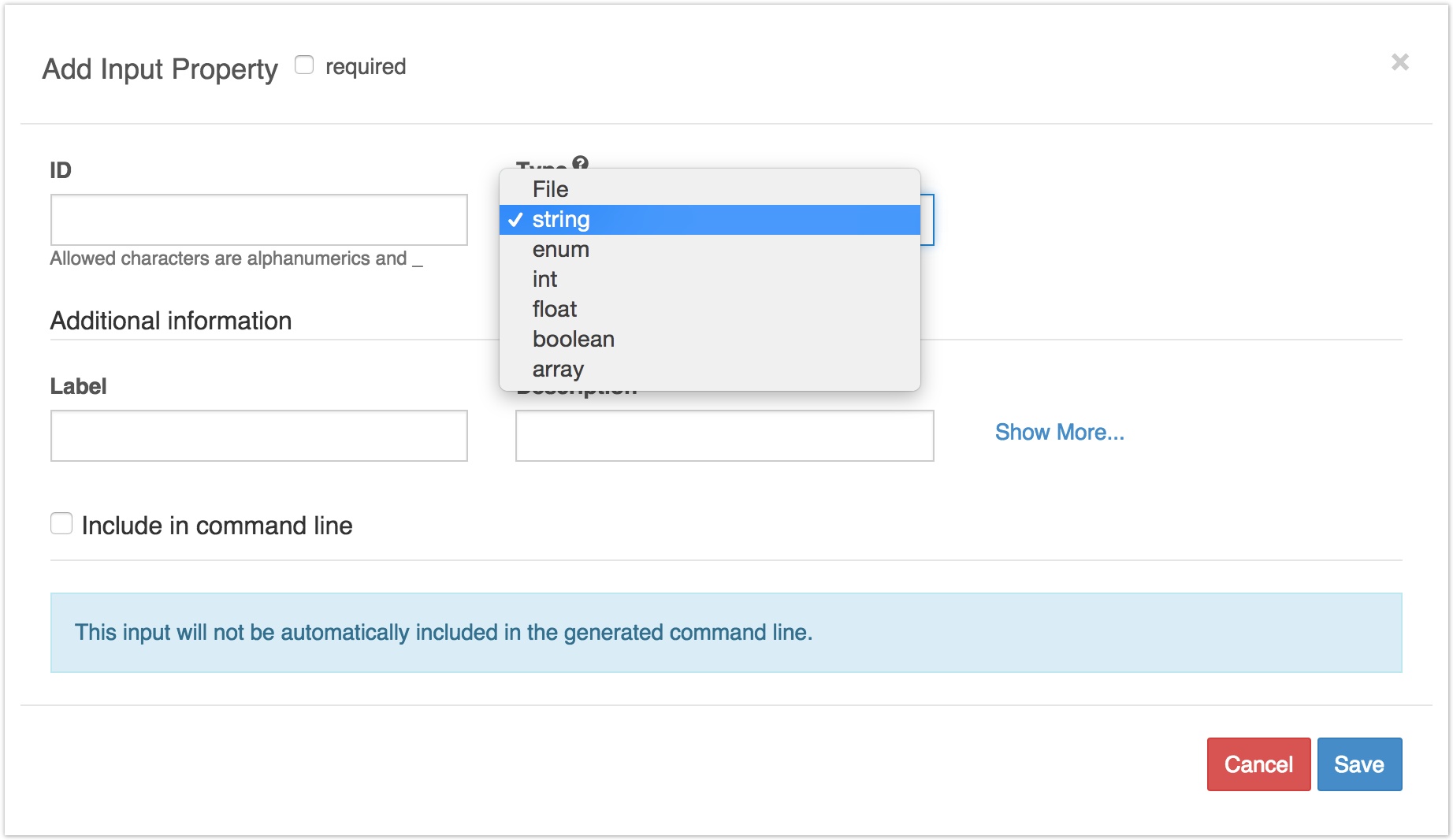
In this window, you can describe an input port.
Basic Information
Required:
If checked, the input has to be provided for every execution of the tool. When providing parameter and input values for execution, if an input is set as required, the input box will indicate that the input needs to be set. If the input is not set, execution of the tool will not be possible.
ID:
This field can be any name you give to identify the port. It will be used to label the port with in other graphical interfaces, like the workflow editor.
Type:
This field specifies the kind of object that should be inputted to the port. The available input types are:
- File - Specify a file as the input.
- string - Specify a string as the input.
- enum - Specify a value from a range of restricted values as the input.
- int - Specify an integer as the input.
- float - Specify a fractional value as the input.
- boolean - Specify a Boolean data type as the input.
- array - Specify a collection of related inputs of the same type. Learn more.
- map - Specify a key-value pair as the input, where the keys and values are strings.
- record - Specify a collection of related inputs with varying types.
##Additional Information
###Label and Description:
These fields allow you to add more information to describe the function of the input port. Information entered into these fields is just for your own labelling purposes, and doesn't affect the execution of the tool.
Command line binding for inputs
If the data taken by the input port is fed into your tool as an option argument on the command line, then you should check the box marked Include in command line. This allows you to describe the format of the option and to specify the value that is passed in as the option argument. The way to describe the command line option is the same as for the ∫ field on the General Information tab:
Position: This refers to the position of the command option on the command line relative to the base command. For example, '1' indicates that the option should be entered first, after the base command.
Prefix: This refers to a command option that the base command can take to indicate inputs.
Separate prefix with: This allows you to specify the character that separates the prefix from the option argument: it can be either a space, or the empty string (i.e. no character separates prefix from the option argument). Note that if your command requires a separator other than space or the empty string, such as '=', you can enter this directly after the prefix and set the separator to the empty string.
Value: This refers to the fixed or dynamic expression passed in as the option argument for the option given in Prefix.
- If the Value field is left empty, you can pass in a value as the option argument for each execution of the tool.
- If the Value field contains a fixed value (such as an integer, string, etc) then it will be passed as the value of the option argument for every execution.
- Alternatively, the Value field can take a dynamic value, which is a JavaScript expression involving variables that refer to features of the execution. More details are contained in the tipbox below:
Using dynamic expressions to give input values
Suppose that your tool receives data—say, from a tool upstream in a workflow—that is not quite in the format that it expects. For example, your tool may expect just file names, not entire file paths, to be included in the command line, but may be passed file paths as inputs.
In cases like this, you can use string manipulation on the strings representing items that are inputted to the tool, in order to alter the string that is passed to the command line as the input for the port.
For more details, see the F4C documentation on dynamic expressions in the Tool Editor.
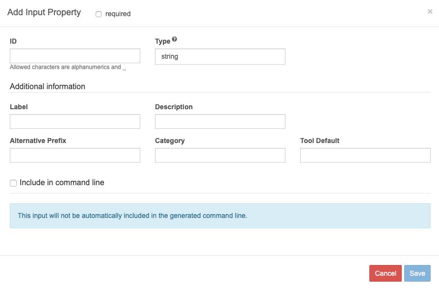
Extra fields on the inputs tab
These fields are available:
###Alternative Prefix:
If your tool inputs are included on the command line using a prefix (command option), and you have specified this in the command line bindings, you can include the alternative prefix here. This would typically be the long prefix.
###Tool Default:
In this field, you can enter a brief description of what the tool does by default. This is just for the purpose of labelling the tool in the workflow editor; it doesn't affect functioning.
Category: You can enter a keyword that describes the tool. Again, this is just for labelling purposes.
File types
When the Input type is set to File or array of files, the Tool Default field changes to File Types. The value entered in the File Types field is mainly used for prefiltering files before execution and should be entered in the following format:
<extension>,<extension> - e.g. BAM,SAM with no spaces after the comma.
Another use of File Types is when connecting input and output ports in a workflow: while making a connection, the drag-and-drop functionality will show green nodes for input ports with matching file types and red ones where the file types don't match.
STAGE INPUT

Stage input
The settings under Stage Input allow you to make a tool's input files available in the tool's working directory.
Files that are named as inputs to a tool are not, by default, in the tool's working directory. In most workflows this access is sufficient, since most tools only need to read their input files, process the data contained in them, and write new output files on the basis of this data to their working directory. However, in some cases a tool might require input files to be in its working directory, and this is where the Stage Input option is used.
Stage Input allows you to modify the way files appear in a tool's working directory in two ways:
- Copy files that are input to a tool to that tool's working directory. This makes the files directly available in the working directory.
- Link the files input to a tool to that tool's working directory, using a symbolic link (symlink). This option is used in the following circumstances:
- To 'pass the files through' the tool, and report them as the tool's outputs, without actually modifying the files.
- To simplify the relative path of the input files to the tool. If you need to include the file paths of a tool's input files as arguments passed to the tool, the path will be simpler if there is a symbolic link from the input files to the tool's working directory.
Please note that while a tool on the F4C cannot create output files outside its own working directory, it may write other files – such as config files – outside the working directory. This means that you don't need to modify a tool that is configured to write files to a different directory, so long as you do not wish to treat those files as outputs.
Files that are copied or linked using the Stage Input option will not be produced as the tool's outputs unless output port(s) are created specifically for them.
Consider the following diagram:
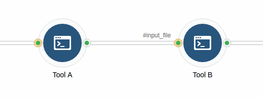
In this example, files are input to Tool B from Tool A. If Tool B needs the input files to be available in its working directory, you need to use the Stage Input setting on the #input_file input port on Tool B.
To copy the input files from Tool A to the working directory of Tool B, in order to modify them:
- Open Tool B in the Tool Editor.
- On the Inputs tab, click the tool description for the inputs port #input_file.
- Click Stage Input and select Copy from the dropdown menu,
To create symbolic links for the input files into the working directory of Tool B, in order to pass them through, along with other output files but not modify them:
- Open Tool B in the Tool Editor.
- On the Inputs tab, click the tool description for the inputs port #input_file.
- Click Stage Input and select Link from the dropdown menu,
Since the Link option only results in creation of a symbolic link, it is generally faster than Copy. However, Copy might be required in certain cases. Besides writing data to files produced by other tools, you also need to select Copy when the tool you are configuring needs to add the output files of the previous tool in the workflow to an archive. In order to be able to archive the files, you need actual copies of the files in the tool's working directory.
To see how the Stage Input option is used in an actual workflow on the F4C:
VarScan2 Workflow from BAM is a public workflow that contains a tool named SAMtools Index FASTA. This tool indexes a sequence in FASTA format and outputs a FAI index file. It is also able to output the FASTA file that has been provided as its input.
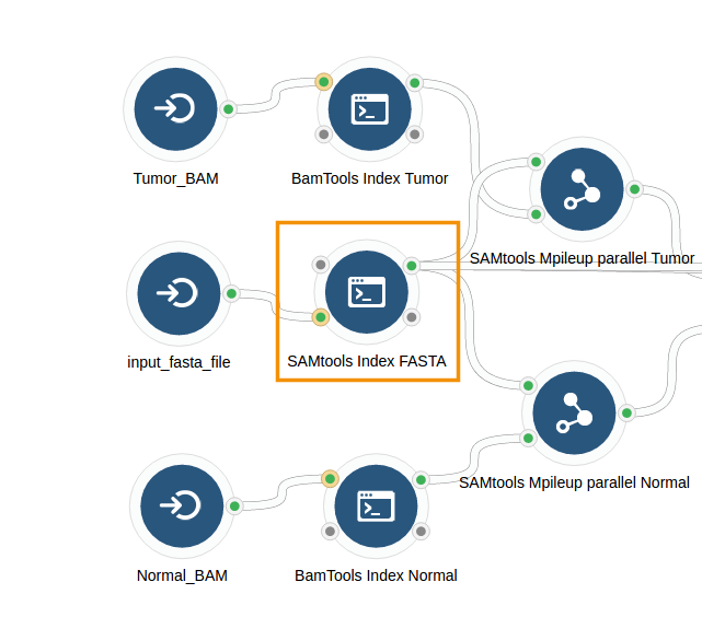
To output the FASTA file that is used as the SAMTools Index FASTA's input file, configure the #input_fasta_file input port as Stage Input > Link. This creates a symbolic link to the input FASTA file in the working directory of SAMtools Index FASTA and the tool passes the FASTA file as its output, along with the generated index file.
LOAD CONTENTS
In the context of an input port for files, the $self object is a JavaScript object referring to the file objects, which can be used in the Value field (see the documentation on dynamic expressions in tool descriptions for details).
Checking the box marked Load Contents on the inputs tab adds an additional property to $self, namely contents, which refers to the first 64kb of the file contents.
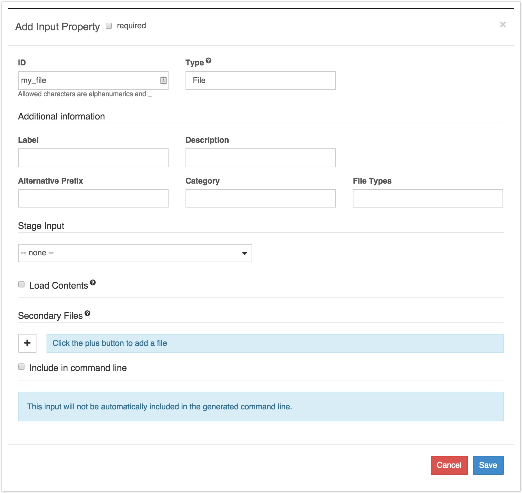
Secondary files
This field is present if the input type is File or Array of files. It allows you to define the extension to be appended to the name of the input file to get the name of the secondary file that is to be loaded automatically along with the input file on this input port. For example, if the input file is input.bam and you enter .bai in the Secondary File field, the resulting file path will be input.bam.bai. If you want to remove an extension from the input file name before adding the secondary file extension, add a caret ^ for each extension you want to remove. For example, if the input file is input.bam and you enter ^.bai in the Secondary File field, then the secondary file path will be input.bai.
If a secondary file is defined for an input port, the Include in command line box will always be automatically checked when you save and reload the input port editor. This behavior corresponds to the specification of the CWL version that is implemented on the F4C. If you do not want to include this input port in the command line, set the Value field to return no value by populating it with an expression such as:
{
    return "";
}
Example
Suppose that I had uploaded BWA Mem to the F4C, and was describing it in the tool editor. Then, I would need to add as many input ports as the tool has inputs. In particular, I would add an input port for the thread number to be inputted.
The prefix for thread number on BAW Mem is -t. If I wanted to be able to set the thread number every time I used the tool, I would configure its input port description as follows:
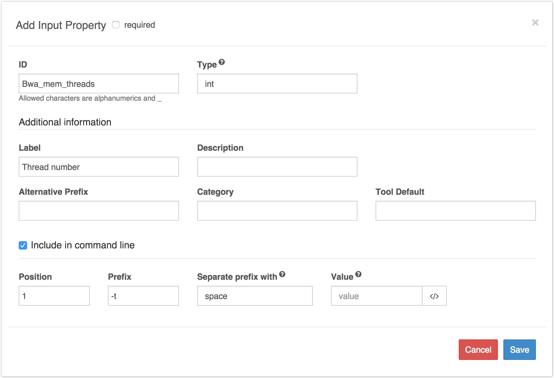
Example of describing a tool input port
Updated less than a minute ago
